Recent Posts

Blogroll

                                          My PIC12F683 Development Board
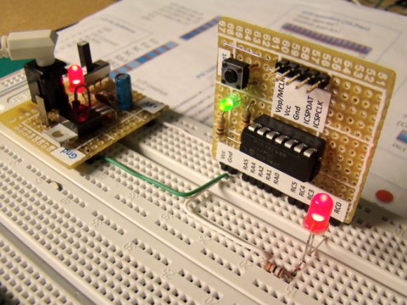
Office Map Circuit diagram for each experiment may not be available separately because they are conducted with PIC12F683 development board that I made. So, the readers should first see the schematic of my development board.

Saturday, September 25, 2010

Experiment No. 6: PIC12F683 Timer1 used as a Frequency Counter

Objective: Determine the frequency of an external clock source (0-65535 Hz), send it to PC through serial port, and display it on a hyperterminal application window.

Introduction

The Timer1 module in PIC12F683 is a 16-bit timer/counter. It can operate as Timer or as a synchronous/asynchronous counter. In asynchronous mode, the Timer1 will increment at the arrival of each external clock pulse at T1CKI port. Whereas, in synchronous mode the input clock pulse to Timer1 module is synchronized to the microcontroller internal clock. A dedicated control register, T1CON, is available to set-up and control the Timer1 module. We are going to use the counter feature of it to measure the frequency of an external clock source. The Timer1 register pair (TMR1H:TMR1L) increments from 0000h to FFFFh and rolls over to 0000h. When Timer1 rolls over, it indicates timer overflow by setting Timer1 interrupt flag (TMR1IF) bit of PIR1 register. To enable the interrupt on rollover, following bits must be set:
  • Timer1 interrupt enable (TMR1IE) bit of PIE1 register (PIE1 = 01h could do that)
  • PEIE and GIE bits of the INTCON register (INTCON = C0h could do that)
Since the 16-bit counter can count up to 65535, the external clock source with frequency higher than this will overflow the Timer1 counter, and generate the Timer1 overflow interrupt. The external clock source will be obtained from a 555 Timer IC operating as an astable multivibrator, and will be fed to GP5/T1CKI pin (2) of PIC12F683. Once I made a 555 experiment board for myself, I am going to use the same. In this board I can vary the frequency of the multivibrator using a potentiometer. Search internet for more detail on 555 astable multivibrator.

My 555 Timer IC Experiment Board

Friday, August 27, 2010

A Versatile Temperature Data Logger using PIC12F683 and DS1820

Introduction
There are varieties of digital temperature logger projects available online based on different microcontrollers. The one I am going to talk about is based on a Microchip's 8-pin microcontroller, PIC12F683. It reads temperature values from a DS1820 digital sensor and stores in its internal EEPROM. PIC12F683 has 256 bytes of internal EEPROM and we are going to store the temperature values in 8-bit format. This means only the eight most significant bits of temperature data from DS1820 will be read and as such the temperature resolution will be of 1 degree C.

My temperature logger has following features:
  • Reads temperature from a DS1820 sensor and stores in the internal EEPROM locations.
  • Can store up to 254 temperature values. EEPROM location 0 is used to store the sampling interval, and location 1 is used to store the number of records.
  • Three sampling interval options: 1 sec, 1 min, and 10 min. This can be selected during powering up.
  • Start and Stop buttons for control operations.
  • The recorded temperature values can be sent to PC through a serial port. A separate Send button is available to initiate data transfer.
  • A LED to indicate various ongoing operations.
  • Reset button to clear all previous records.  

Saturday, July 31, 2010

Experiment No. 5: DC Motor Speed Control using Pulse Width Modulation (PWM)

Introduction

PIC12F683 has a built-in PWM module. The PWM output (CCP1 pin) is multiplexed with GPIO.2 (pin 5). So the TRISIO<2> bit must be cleared to make the CCP1 pin an output.
The objective of this experiment is to control the speed of a DC motor with an input from a potentiometer. This will be achieved in two steps:
  • Read analog value (potentiometer output) through AN0 channel and generate a PWM wave at CCP1 pin (5) with duty cycle proportional to the analog value.
  • Feed the PWM to motor driver transistor and observe the speed.
mikroC library routines for PWM
PWM1_Init
PWM1_Set_Duty
PWM1_Start
PWM1_Stop

Since PWM1_Set_Duty library function takes duty cycle input as an 8-bit integer, the digital value of analog signal, which is 10-bit, must be converted to 8-bit first. This will give 256 speed levels (0-255).

Experimental Setup
Connect POT2 output to pin 7 (AN0) of PIC12F683 and pin 5 (CCP1) to the input of motor driver transistor.

Online Embedded Systems Lab

This online laboratory teaches you the fundamentals of microcontroller-based embedded system development through a series of laboratory exercises. Most of the time, students and hobbyists could not afford expensive development kits and software to learn these things. These tutorials are prepared such that you will be building microcontroller projects at a minimum cost. Check this out