Objective: Determine the frequency of an external clock source (0-65535 Hz), send it to PC through serial port, and display it on a hyperterminal application window.
Introduction
The Timer1 module in PIC12F683 is a 16-bit timer/counter. It can operate as Timer or as a synchronous/asynchronous counter. In asynchronous mode, the Timer1 will increment at the arrival of each external clock pulse at T1CKI port. Whereas, in synchronous mode the input clock pulse to Timer1 module is synchronized to the microcontroller internal clock. A dedicated control register, T1CON, is available to set-up and control the Timer1 module. We are going to use the counter feature of it to measure the frequency of an external clock source. The Timer1 register pair (TMR1H:TMR1L) increments from 0000h to FFFFh and rolls over to 0000h. When Timer1 rolls over, it indicates timer overflow by setting Timer1 interrupt flag (TMR1IF) bit of PIR1 register. To enable the interrupt on rollover, following bits must be set:
- Timer1 interrupt enable (TMR1IE) bit of PIE1 register (PIE1 = 01h could do that)
- PEIE and GIE bits of the INTCON register (INTCON = C0h could do that)
Since the 16-bit counter can count up to 65535, the external clock source with frequency higher than this will overflow the Timer1 counter, and generate the Timer1 overflow interrupt. The external clock source will be obtained from a 555 Timer IC operating as an astable multivibrator, and will be fed to GP5/T1CKI pin (2) of PIC12F683. Once I made a 555 experiment board for myself, I am going to use the same. In this board I can vary the frequency of the multivibrator using a potentiometer. Search internet for more detail on 555 astable multivibrator.
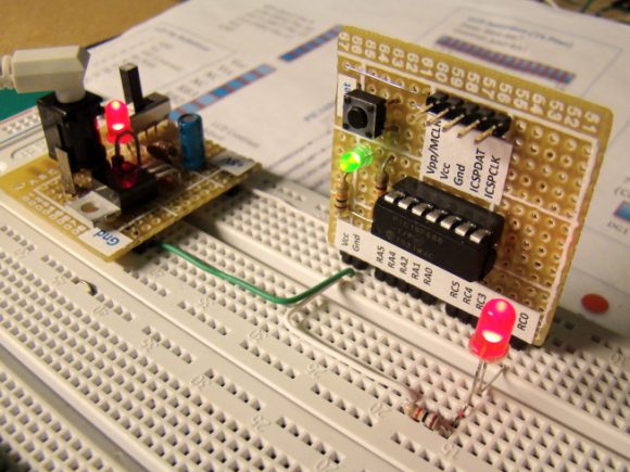
My 555 Timer IC Experiment Board