PIC12F683 is a 8-pin Flash based, 8bit RISC microcontroller from Microchip. This little PIC microcontroller offers up to 6 I/O pins (the remaining two are power supply pins). It needs no external oscillator, as it has an in-built oscillator with software selectable frequency from 8 MHz to 125 KHz. It also offers a feature that allows external signals to wake it upfrom the sleep state. Here are the various features as mentioned on the datasheet.
High-Performance RISC CPU:
• Only 35 instructions to learn:
All single-cycle instructions except branches
• Operating speed:
- DC – 20 MHz oscillator/clock input
- DC – 200 ns instruction cycle
• Interrupt capability
• 8-level deep hardware stack
• Direct, Indirect and Relative Addressing modes
Special Microcontroller Features:
• Precision Internal Oscillator:
- Factory calibrated to ±1%, typical
- Software selectable frequency range of 8 MHz to 125 kHz
- Software tunable
- Two-Speed Start-up mode
- Crystal fail detect for critical applications
- Clock mode switching during operation for power savings
• Power-Saving Sleep mode
• Wide operating voltage range (2.0V-5.5V)
• Industrial and Extended temperature range
• Power-on Reset (POR)
• Power-up Timer (PWRT) and Oscillator Start-up Timer (OST)
• Brown-out Reset (BOR) with software control option
• Enhanced Low-Current Watchdog Timer (WDT) with on-chip oscillator (software selectable nominal 268 seconds with full prescaler) with software enable
• Multiplexed Master Clear with pull-up/input pin
• Programmable code protection
• High Endurance Flash/EEPROM cell:
- 100,000 write Flash endurance
- 1,000,000 write EEPROM endurance
- Flash/Data EEPROM Retention: > 40 years
Peripheral Features:
• 6 I/O pins with individual direction control:
- High current source/sink for direct LED drive
- Interrupt-on-pin change
- Individually programmable weak pull-ups
- Ultra Low-Power Wake-up on GP0
• Analog Comparator module with:
- One analog comparator
- Programmable on-chip voltage reference (CVREF) module (% of VDD)
- Comparator inputs and output externally accessible
• A/D Converter:
10-bit resolution and 4 channels
• Timer0:
8-bit timer/counter with 8-bit programmable prescaler
• Enhanced Timer1:
- 16-bit timer/counter with prescaler
- External Timer1 Gate (count enable)
- Option to use OSC1 and OSC2 in LP mode as Timer1 oscillator if INTOSC mode selected
• Timer2: 8-bit timer/counter with 8-bit period register, prescaler and postscaler
• Capture, Compare, PWM module:
- 16-bit Capture, max resolution 12.5 ns
- Compare, max resolution 200 ns
- 10-bit PWM, max frequency 20 kHz
• In-Circuit Serial Programming™ (ICSP™) via two pins
The I/O port of PIC12F683 is called the GPIO (
general
purpose
input/
output file register), and the corresponding data direction register is TRISIO. It works mostly the same way as ports in other PIC microcontrollers. Setting a TRISIO bit (= 1) will make the corresponding GPIO pin an input, and clearing the TRISIO bit (= 0) will make it an output. One important thing to note is that GP3 is input only pin, and cannot be configured as an output.
PIC12F683 has a 13-bit program counter that can address up to 8K x 14 program memory, but only the first 2K x 14 (0000h-07FFh) is physically implemented. PIC12F683 also has 256 bytes of data EEPROM with an address range from 0h to FFh.
For details, read the
datasheet.

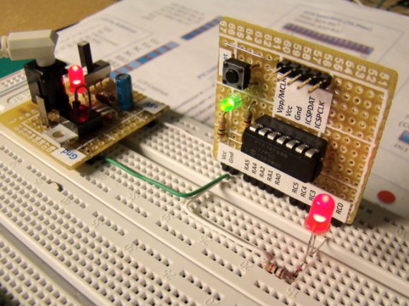
 Circuit diagram for each experiment may not be available separately because they are conducted with PIC12F683 development board that I made. So, the readers should first see the schematic of my development board.