
Introduction
The Timer1 module in PIC12F683 is a 16-bit timer/counter. It can operate as Timer or as a synchronous/asynchronous counter. In asynchronous mode, the Timer1 will increment at the arrival of each external clock pulse at T1CKI port. Whereas, in synchronous mode the input clock pulse to Timer1 module is synchronized to the microcontroller internal clock. A dedicated control register, T1CON, is available to set-up and control the Timer1 module. We are going to use the counter feature of it to measure the frequency of an external clock source. The Timer1 register pair (TMR1H:TMR1L) increments from 0000h to FFFFh and rolls over to 0000h. When Timer1 rolls over, it indicates timer overflow by setting Timer1 interrupt flag (TMR1IF) bit of PIR1 register. To enable the interrupt on rollover, following bits must be set:
- Timer1 interrupt enable (TMR1IE) bit of PIE1 register (PIE1 = 01h could do that)
- PEIE and GIE bits of the INTCON register (INTCON = C0h could do that)

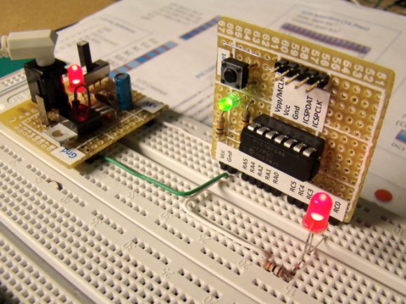
My 555 Timer IC Experiment Board
Since, we need to determine the frequency of an external clock source, we will use Timer1 as an asynchronous counter. This requires proper setting of T1CON register bits shown below.

So, for our purpose, we are going to set T1SYNC, TMRCS, and TMR1ON bits to turn the Timer1 counter ON and clear TMR1ON to stop the counter.
PIC12F683 Port Settings
GP5/T1CKI : Feed + 5V peak external clock source (input)
GP4 : Serial data transfer to PC (output)
GP3 : Serial data receive from PC (input, not used but needed to be defined while using software UART library routines of mikroC)
This gives TRISIO = 28h
Programming Sequence
- Disable comparator inputs (CMCON0 = 07h).
- Define TRISIO = 28h.
- Disable analog inputs (ANSEL = 00h).
- Enable GIE and PEIE interrupts (INTCON = C0h).
- Enable TMR1 interrupt (PIE1 = 01h).
- Initialize software UART, 9600 baud at GP4 port.
- Do {
Start Timer1 (T1CON = 7)
Wait 1 sec
Stop Timer1 (T1CON = 6)
If Timer1 overflow, send message "Frequency Out of Range" and clear TMR1IF flag
Else,
Frequency = (TMR1H << 8) + TMR1L
Display Frequency
} While (1)
Experimental Setup
Connect uTx pin to GP4 port, and external clock source to GP5 port. Also connect Rx, Tx, and Gnd pins to corresponding pins of RS232 port of PC. Open a new hyperterminal window with following settings:
- bps : 9600
- Databits: 8
- Parity : None
- Stop Bits : 1
- Flow Control : Hardware

/*
PIC12F683 Experiment Board
Experimen No. 6 : Frequency Counter 0-65535 Hz
display on Hyperterminal window on PC using Software UART.
Date: 09/25/2010
Clock input to Timer1 (GP5, pin 2, input)
UART Tx = GP4, pin 3, output; output; RX = GP3, input
*/
char Message1[] = "Frequency (Hz) =";
char Message2[] = "Frequency Over Range";
unsigned int frequency, backup=0 ;
char *temp = "00000", error;
unsigned short i, TMR1_OverFlow=0;
void LineFeed(){
Soft_UART_Write(10); // Line Feed
Soft_UART_Write(13); // Carriage Return
}
void interrupt(void){
if(PIR1.TMR1IF) {
TMR1_OverFlow = 1;
PIR1.TMR1IF = 0;
}
}
void main() {
CMCON0 = 7; // Disable comparators
TRISIO = 0b00101000; // GP3, and 5 Inputs; Rest are O/Ps
ANSEL = 0x00; // No analog inputs
GPIO = 0;
INTCON = 0b11000000 ; // Enable GIE and PEIE for Timer1 overflow interrpt
PIE1 = 0b00000001 ; // Enable TMR1IE
// Define GPIO.3 as UART Rx, and 4 as Tx
error = Soft_UART_Init(&GPIO,3, 4, 9600, 0 );
Delay_ms(100);
do {
TMR1H = 0x00;
TMR1L = 0x00;
T1CON = 0b00000111; // Enable Timer 1
Delay_ms(1000);
T1CON = 0b00000110; // Disable Timer 1
frequency = TMR1H;
frequency = frequency << 8 ;
frequency = frequency + TMR1L ;
if(TMR1_OverFlow){
for (i=0; i<= 19; i++) {
Soft_UART_Write(Message2[i]);
Delay_ms(50);
}
LineFeed();
TMR1_OverFlow = 0;
}
else {
if(frequency != backup) {
temp[0] = frequency/10000 + 48;
temp[1] = (frequency/1000)%10 + 48;
temp[2] = (frequency/100)%10 + 48;
temp[3] = (frequency/10)%10 + 48;
temp[4] = frequency%10 + 48;
for (i=0; i<= 15; i++) {
Soft_UART_Write(Message1[i]);
Delay_ms(50);
}
for (i=0; i<= 4; i++) {
Soft_UART_Write(temp[i]);
Delay_ms(50);
}
LineFeed();
}
}
delay_ms(100);
backup = frequency;
} while(1);
}
Output
My 555 timer board can generate frequency from approximately 1 KHz to over 100 KHz by a varying 100K potentiometer. Here's a snapshot of few frequency measurements shown on the hyperterminal window.

Application of this idea
You can extend this idea to make a frequency counter of higher range. Higher frequency measurements can be achieved by incrementing a user defined variable (say X) every time the Timer1 overflows. At the end of 1 sec gate interval, you can compute the frequency as 65535*X + current Timer1 value.
0 comments:
Post a Comment