
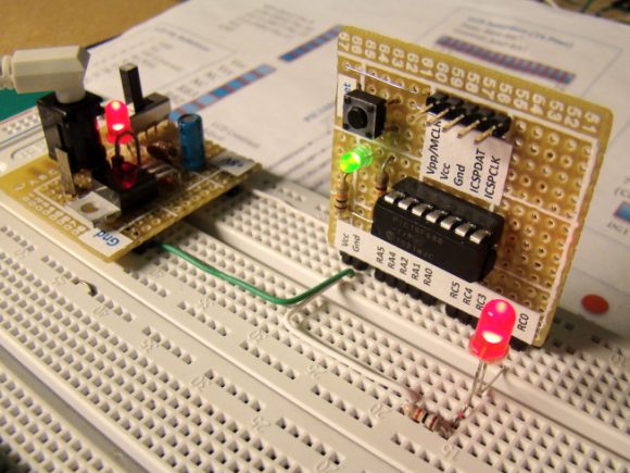
Our purpose here is to explore the potential of PIC12F683 microcontroller for which we need a development board. The good thing is we are going to make our own board. The schematic and the actual board that I have built are shown below. I soldered all the components on a 12 x 8 cm general purpose prototyping board.

Completed Board
It has following features in it:
1. A Regulated +5V power supply.
2. 3 Output LEDs that can be connected to any GPIO pins using jumper wires.
3. ON/OFF power supply switch.
4. A Green LED as a power ON indicator.
5. An 8-pin IC socket for PIC12F683 microcontroller.
6. Two potentiometers: one for providing Vref, and other for simulating analog input to ADC.
7. An ICSP header connector.
8. Two tactile switches for input operation.
9. A TTL to RS232 level shifter using a transistor circuit.
10. A piezo buzzer.
11. A DC motor with driving circuit.
Most of these features on the board are accessible through female header pins. None of the 6-I/O pins of PIC12F683 are hardwired to anything and they are accessible through header pins too. Only the ISCP pins are accessible through male header pins. Figures below show PIC12F683 ports, header pins that I used and schematic of the development board.


Figure 2. My PIC12F683 Development Board
List of things needed:
Description:
As you see the output LEDs have 470Ω current limiting resistors in series so that a PIC pin can be safely drive them. The piezo buzzer is also driven directly by a PIC pin through a series resistor. The DC motor, however, is connected as a load to the collector of S8050 transistor as the required current to drive the motor cannot be supplied by the PIC port. So, the PIC port can switch on the transistor by pulling its base HIGH and the collector current of the transistor provides the sufficient current to drive the motor.
The TTL to RS232 level converter and vice-versa is achieved with two transistors and few other components. The negative voltage required for RS232 level (for logic '1') is stolen from the RS232 port of PC itself. Note that there is no hardware UART inside PIC12F683, so the serial data transfer from the microcontroller to PC will be possible only through a software UART through any of GP0, GP1, GP2, GP4, and GP5 ports (GP3 is input only). The transmitter and receiver port on microcontroller side are denoted by uTx and uRx, whereas on the PC side are denoted by Tx and Rx, respectively.
The circuit diagram shows that the two input tact switches with the two potentiometer outputs and all the eight PIC12F683 pins are accessible through female headers. The tact switches are active low, i.e., under normal condition, a tact switch output is HIGH and when it is pressed, the output is LOW. There are couple of extra headers for Vcc and Gnd terminals which may be required while doing experiments.
The power supply circuit is the standard circuit of 7805 regulator IC. A power-on LED is connected across Vcc and Gnd with a 470Ω series resistor.
The in-circuit serial programming (ICSP) of PIC12F683 can be done with two pins: ICSPDAT (pin 7), and ICSPCLK (pin 6). The programming voltage, Vpp, should be provided to pin 4 of PIC12F683 while programming. All the required ISCP pins are available through a male header, so the PIC can be programmed through any ICSP PIC programmer. Make sure that the sequence of ISCP pins on the programmer side and our learning board match.
Important: During ICSP, pins 4, 6, and 7 of PIC12F683 should not be connected to anything; leave them open so that there won't be any voltage conflict between the programmer and the external circuit.
Note: Turn OFF the power supply switch during ICSP programming.
Software:
If you have made this board, get ready to have fun! You can write your experimental programs for PIC12F683 in assembly or high level language. But for the experiments that I am going to demonstrate here, I am using the free version of mikroC compiler from MikroElektronica. It is a C compiler for PIC microchips, and the free version limits output program size to 2K. But we don't need more than that for PIC12F683.


- 3 general purpose Red LEDs
- 1 green LED
- 1 PIC12F683 microcontroller
- 1 8-pin IC socket
- 1 7805 regulator IC
- 1 DC adapter socket
- 1 BC557 PNP transistor
- 1 S8050 (or BC547 will work too) NPN transistor
- 1 piezo buzzer
- 1 5V DC motor (I got one from an old CD player)
- 2 5K potentiometers (I got from an old TV circuit board)
- 2 Tactile switches
- Male and Female header pins as required
- 3 10uf, 50V electrolyte capacitor
- 1 0.1uf capacitor
- 3 general purpose diodes
- 2 4.7K resistances
- 3 330 Ohms resistances
- 3 10K resistances
- 1 1K resistance
- 1 470 Ohm resistance
- 1 1.5K resistance
Description:
As you see the output LEDs have 470Ω current limiting resistors in series so that a PIC pin can be safely drive them. The piezo buzzer is also driven directly by a PIC pin through a series resistor. The DC motor, however, is connected as a load to the collector of S8050 transistor as the required current to drive the motor cannot be supplied by the PIC port. So, the PIC port can switch on the transistor by pulling its base HIGH and the collector current of the transistor provides the sufficient current to drive the motor.
The TTL to RS232 level converter and vice-versa is achieved with two transistors and few other components. The negative voltage required for RS232 level (for logic '1') is stolen from the RS232 port of PC itself. Note that there is no hardware UART inside PIC12F683, so the serial data transfer from the microcontroller to PC will be possible only through a software UART through any of GP0, GP1, GP2, GP4, and GP5 ports (GP3 is input only). The transmitter and receiver port on microcontroller side are denoted by uTx and uRx, whereas on the PC side are denoted by Tx and Rx, respectively.
The circuit diagram shows that the two input tact switches with the two potentiometer outputs and all the eight PIC12F683 pins are accessible through female headers. The tact switches are active low, i.e., under normal condition, a tact switch output is HIGH and when it is pressed, the output is LOW. There are couple of extra headers for Vcc and Gnd terminals which may be required while doing experiments.
The power supply circuit is the standard circuit of 7805 regulator IC. A power-on LED is connected across Vcc and Gnd with a 470Ω series resistor.
The in-circuit serial programming (ICSP) of PIC12F683 can be done with two pins: ICSPDAT (pin 7), and ICSPCLK (pin 6). The programming voltage, Vpp, should be provided to pin 4 of PIC12F683 while programming. All the required ISCP pins are available through a male header, so the PIC can be programmed through any ICSP PIC programmer. Make sure that the sequence of ISCP pins on the programmer side and our learning board match.
Important: During ICSP, pins 4, 6, and 7 of PIC12F683 should not be connected to anything; leave them open so that there won't be any voltage conflict between the programmer and the external circuit.
Note: Turn OFF the power supply switch during ICSP programming.
Software:
If you have made this board, get ready to have fun! You can write your experimental programs for PIC12F683 in assembly or high level language. But for the experiments that I am going to demonstrate here, I am using the free version of mikroC compiler from MikroElektronica. It is a C compiler for PIC microchips, and the free version limits output program size to 2K. But we don't need more than that for PIC12F683.
We will use the following configuration bits for PIC12F683.
Oscillator : Internal RC, No Clock
WDT OFF
Master Clear Disabled
WDT OFF
Master Clear Disabled
For all the experiments demonstrated here, use internal clock at 4.0 MHz.
In mikroC, you can select these in Edit Project window.
More Snapshots


2 comments:
VERY NICE.....
I think i am going to create one of these myself!!! I have so many issues while bread boarding with the pins of the wires sometimes not making contact.... Thanks again, for all your information.
Cool Project. You're great!
discounted digital board
Post a Comment