
HD44780 based character LCD displays are very popular among hobbyists. They are easy to interface with microcontrollers and most of the present day high-level compilers have in-built routines for them. However, the bad part is at least 6 I/O pins of microcontroller are required to use them in your project. Therefore, they are not applicable for 8-pin devices like PIC12F series microchips. The aim of this project is to allow LCD interfacing to such devices using 3-wires. I am going to demonstrate this with PIC12F683 microcontroller. The character data or command from the microcontroller will be transferred serially to an 8-bit serial-in parallel-out shift register (74HC595), and the parallel output will be fed to the LCD driver pins.

About 74HC595
74HC595 is a high-speed 8-bit serial in, serial or parallel-out shift register with a storage register and 3-state outputs. The shift register and storage registers have separate clocks, SH_CP and ST_CP respectively. Data in the shift register is shifted on the positive-going transitions of SH_CP, and the content of shift register will be transferred to the storage register on a positive-going transition of the ST_CP. If we tie both the clocks together, the shift register will always be one clock ahead of the storage register. The 8-bit data of the storage register will appear at the parallel output (Q0-Q7) when the output enable (OE) is low.

In this project, SH_CP and ST_CP are tied together. So, if we want to receive a serially transferred 8-bit into parallel form at Q0-Q7, an extra clock pulse is required after transmitting the 8-th bit of serial data because the clocks are tied and the storage register is 1-clock behind the shift register.
HD44780-based character LCD
All HD44780 based character LCD displays are connected using 14 wires: 8 data lines (D0-D7), 3 control lines (RS, E, R/W), and three power lines (Vdd, Vss, Vee). Some LCDs may have LED backlight and so they may have additional connections (usually two: LED+ and LED-).
Pin Description
Control pins
The control pin RS determines if the data transfer between the LCD module and an external microcontroller are actual character data or command/status. When the microcontroller needs to send commands to LCD or to read LCD status, it must be pulled low. Similarly, this must be pulled high if character data is to be sent to and from the LCD module.
The direction of data transfer is controlled by the R/W pin. If it is pulled Low, the commands or character data is written to the LCD module. And, when it is pulled high, the character data or status information from the LCD registers is read. In this project, we will use one way data transfer, i.e., from microcontroller to LCD module, so the R/W pin will be grounded permanently.
The enable pin (E) initiates the actual data transfer. When writing to the LCD display, the data is transferred only on the high to low transition of the E pin.
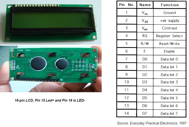
Power supply pins
Although most of the LCD module data sheets recommend +5V d.c. supply for operation, some LCDs may work well for a wider range (3.0 to 5.5 V). The Vdd pin should be connected to the positive power supply and Vss to ground. Pin 3 is Vee, which is used to adjust the contrast of the display. In most of the cases, this pin is connected to a voltage between 0 and 2V by using a preset potentiometer.
Data pins
Pins 7 to 14 are data lines (D0-D7). Data transfer to and from the display can be achieved either in 8-bit or 4-bit mode. The 8-bit mode uses all eight data lines to transfer a byte, whereas, in 4-bit mode, a byte is transferred as two 4-bit nibbles. In the later case, only the upper 4 data lines (D4-D7) are used. This technique is beneficial as this saves some input/output pins of microcontroller.
For further details on LCDs, I recommend to read these two articles first from Everyday Practical Electronics magazine : How to use intelligent LCDs
Part 1: http://lcd-linux.sourceforge.net/pdfdocs/lcd1.pdf
Part 2. http://lcd-linux.sourceforge.net/pdfdocs/lcd2.pdf
Circuit Diagram
The hardware part of this project is fairly simple. The challenging part is to write the driver software that is responsible for a proper sequence of operations required to serially transfer character data and command to 74HC595 serial-in parallel-out shift register. The shift register parallel output is then connected to LCD data lines (D4-D7) and RS control pin. This arrangement requires 3-pins of microcontroller to display character data on a parallel LCD display: 2 pins for providing Clock and Data to 74HC595, and 1 pin for enable control (E) pin of LCD module. Since the data transfer uses 4-bit mode, any 8-bit command or character data is sent in two steps: send the higher nibble first, and then the lower nibble. The R/W control pin is grounded, and therefore no data or status read from the LCD module is possible in this case.

The SH_CP (11) and ST_CP (12) clock inputs of 75HC595 are tied together, and will be driven by one microcontroller pin. Serial data from microcontroller is fed to the shift register through DS (14) pin. OE (13) pin is grounded and reset pin MR (10) is pulled high. Parallel outputs Q0-Q3 from 74HC595 are connected to D4-D7 pins of the LCD module. Similarly, Q4 output serves for RS control pin. If the LCD module comes with a built-in backlight LED, it can simply be turned ON or OFF through LED control pin shown above. Pulling the LED pin to logic high will turn the back light ON. I soldered this circuit on a general prototyping board (shown below).


Software
A bit of data fed to DS pin of 74HC595 appears at Q0 output after 2 clocks (because SH_CP and ST_CP are tied). So, sending 4-bit data (D4-D7) and an RS signal require 6 clock pulses till they appear at Q0-Q4 outputs respectively. When the LCD module is turned ON, it is initialized in 8-bit mode. A number of initializing commands should be sent to operate the LCD module in 4-bit mode. All the driver routines that are discussed here are written in mikroC compiler. They work only for a 16x2 LCD module. User can modify the initialization operations inside the Initialize_LCD() routine to account for other LCD configurations. The driver routines and their functions are described below.
l Initialize_LCD() : It initializes the LCD module to operate into 4-bit mode, 2 lines display, 5x7 size
character, display ON, and no cursor.
l Write_LCD_Data() : Sends a character byte to display at current cursor position.
l Write_LCD_Cmd() : Write a command byte to the LCD module.
l Write_LCD_Nibble() : Data or command byte is sent to the LCD module as two nibbles. So this function
routine takes care for sending the nibble data to the LCD module.
l Write_LCD_Text() : This routine is for sending a character string to display at current cursor position.
l Position_LCD() : To change the current cursor position.
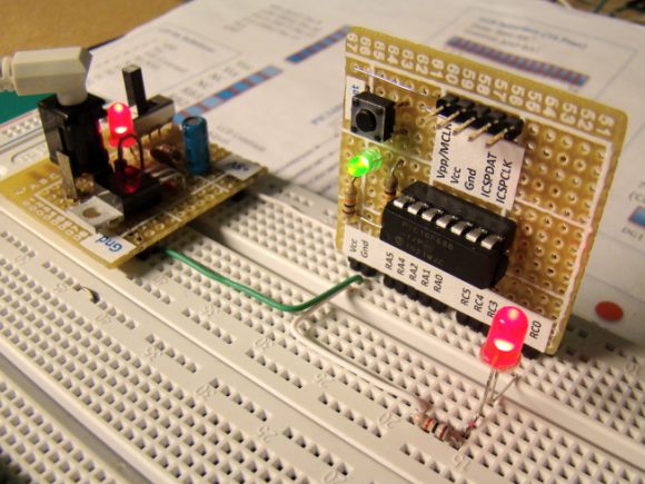
At the beginning of your program, you need to define Data_Pin, Clk_Pin, and Enable_Pin to the chosen microcontroller ports. I am going to demonstrate here how to use these driver routines to display two blinking character strings, Message1 and Message2, at different locations. I am going to test our serial LCD module with a PIC12F683 microcontroller. The test circuit is shown below.
Note: My PIC12F683 Settings
Running at 4 MHz internal clock, MCLR disabled, WDT OFF.
Clock, Data, and Enable lines are served through GP1, GP5, and GP2 ports.


This must be compiled with MikroC Pro for PIC from MikroElektronika.
/* 3-wire Serial LCD using 74HC595
Rajendra Bhatt, Sep 6, 2010
*/
sbit Data_Pin at GP5_bit;
sbit Clk_Pin at GP1_bit;
sbit Enable_Pin at GP2_bit;
// Always mention this definition statement
unsigned short Low_Nibble, High_Nibble, p, q, Mask, N,t, RS, Flag, temp;
void Delay_50ms(){
Delay_ms(50);
}
void Write_LCD_Nibble(unsigned short N){
Enable_Pin = 0;
// ****** Write RS *********
Clk_Pin = 0;
Data_Pin = RS;
Clk_Pin = 1;
Clk_Pin = 0;
// ****** End RS Write
// Shift in 4 bits
Mask = 8;
for (t=0; t<4; t++){
Flag = N & Mask;
if(Flag==0) Data_Pin = 0;
else Data_Pin = 1;
Clk_Pin = 1;
Clk_Pin = 0;
Mask = Mask >> 1;
}
// One more clock because SC and ST clks are tied
Clk_Pin = 1;
Clk_Pin = 0;
Data_Pin = 0;
Enable_Pin = 1;
Enable_Pin = 0;
}
// ******* Write Nibble Ends
void Write_LCD_Data(unsigned short D){
RS = 1; // It is Data, not command
Low_Nibble = D & 15;
High_Nibble = D/16;
Write_LCD_Nibble(High_Nibble);
Write_LCD_Nibble(Low_Nibble);
}
void Write_LCD_Cmd(unsigned short C){
RS = 0; // It is command, not data
Low_Nibble = C & 15;
High_Nibble = C/16;
Write_LCD_Nibble(High_Nibble);
Write_LCD_Nibble(Low_Nibble);
}
void Initialize_LCD(){
Delay_50ms();
Write_LCD_Cmd(0x20); // Wake-Up Sequence
Delay_50ms();
Write_LCD_Cmd(0x20);
Delay_50ms();
Write_LCD_Cmd(0x20);
Delay_50ms();
Write_LCD_Cmd(0x28); // 4-bits, 2 lines, 5x7 font
Delay_50ms();
Write_LCD_Cmd(0x0C); // Display ON, No cursors
Delay_50ms();
Write_LCD_Cmd(0x06); // Entry mode- Auto-increment, No Display shifting
Delay_50ms();
Write_LCD_Cmd(0x01);
Delay_50ms();
}
void Position_LCD(unsigned short x, unsigned short y){
temp = 127 + y;
if (x == 2) temp = temp + 64;
Write_LCD_Cmd(temp);
}
void Write_LCD_Text(char *StrData){
q = strlen(StrData);
for (p = 0; p<q; p++){
temp=StrData[p];
write_lcd_data(temp);
}
}
char Message1[] = "3-Wire LCD";
char Message2[] = "using 74HC595";
void main() {
CMCON0 = 7; // Disable Comparators
TRISIO = 0b00001000; // All Outputs except GP3
ANSEL = 0x00; // No analog i/p
Initialize_LCD();
do {
Position_LCD(1,4);
Write_LCD_Text(Message1);
Position_LCD(2,2);
Write_LCD_Text(Message2);
Delay_ms(1500);
Write_LCD_Cmd(0x01); // Clear LCD
delay_ms(1000);
} while(1);
}
Output

Reference:
- How to use Intelligent Liquid Crystal Displays, by Julyan Ilett, (February, March 1997 EPE)
- Two-wire LCD:ATM18 display for the Elektor AVR Project, by Jurss and Rudolph, (elektor -5/2008)
31 comments:
Lovely ,sir
it is really useful not only for low pin count but many normal 18 pin devices where otherwise the pin reqirement is more for other devices.
Incidentally a One wire 4*4 keyboard from the Tips and tricks application note makes it a complete stand alone unit for many applications.
HOpe to see many more such designs from you dear Rajendra Bhat. All the best
regards
sarma
Thank you, Mr Sarma.
The control pin R/W determines if the data transfer between the LCD module and an external microcontroller are actual character data or command/status.
- industrial light fixtures
Thanks for pointing that. I corrected.
Doesnt Work Dude, tested to compile nothing happend. Testet on 2 Pic´s nothing
Which PIC you tried, and how is your circuit look like? Can you post your program? While compiling, what are your configuration bit settings?
I am getting a compiler error with these lines:
sbit Data_Pin at GP5_bit;
I am using Hi-Tech C Compiler. If I comment those out, I can compile...
Please compile with MikroC Pro for PIC from Mikroelektronica. Download the free version from their website.
I was able to modify my code for hi-tech C. You had used functions only available in MikroC. Thank you for the tutorials and the quick responses, they are greatly appreciate.
:]
I am trying to figure out what you are doing with:
0x20 & 15
0x20/16
I know you need to separate the first 4 bits of binary from the later 4 bits, but how do these two lines grab the first and last 4 bits respectively?
Suppose, you have a number 49h (hexadecimal), and you want to separate the two nibbles as 4 and 9. If you AND 49h with 0fh (15), you will get 9, the lower nibble. 49h is 73 in decimal. If you divide 73 by 16, you will get 4 as an integer quotient. So, you have now the higher nibble. You can think this way too. Divide by two is shifting the number right by 1. If you right shift the number by 4, it is equivalent to divide by 16. So, right shifting an 8-bit number by 4 brings the higher nibble to the lower nibble place.
Hi,
Like the code, youve really helped me on using the shift register (74HC595) question:
in the code, under void Write_LCD_Text(char *StrData) WHY IS THE " in there? just a mistake?
temp="StrData[p];
THanks, Mark
Mark,
It was a typo, thank you for pointing that.
Hi,
I am using the PIC 12F629. I am getting part of the string on line 2 if it is 6 char or less in message2. Line 1 is O.K. ?
Jimmy,
Would you give more details about your problem?
Hi,
The problem is the second line will not display the characters "using 74HC595"?
Jimmy,
How many columns you have in your LCD? Are you using 16x2 or 20x2 LCD?
Hi,
Using 16x2 LCD 411 Tech.. Model 2F16DLNW-S
Hi
I Replaced the 12F629 with 12F675 and all works fine now Thanks Jimmy
Hmm. Can't make it work. Trying with a 16F627 and 628. Tried to rewrite the code in Hi-Tech C at first and also tried to compile in MicroC. Odd. Might be a hardware problem.
Can you send me your code and circuit at rajbex at gmail.com? I will look at it.
Hi! Nice work!
I was trying to convert your code into Hi-Tech compiler because I am used to it but I'm getting an error in this line:
q = strlen(StrData);
The compiler returns an error saying that "srtlen" variable has a problem in the declaration.
I included the string.h and while compiling the MPLAB gets a critical error and ends the compilation without creating the HEX ^^!
I had a similar critical error while using the delay function because the compiler had a bug.
Can you help out?
strlen() is the built-in routine in MikroC to find the length of a string. You should check for the equivalent function in Hi-Tech compiler. I am sorry I have not used Hi-Tech.
A good selection of PIC circuit ideas on
www.artic-instruments.webs.com
Recently, my Lcd tv made me mad. The picture turned white after 10 mins of power on. Could there be circuit board defect? Any ideas.
i convert source to htpic, but it's not display anything..someone help me...thanks!
#include "pic.h"
#include "string.h"
__CONFIG(INTIO & MCLRDIS & WDTDIS);
#define Data_Pin GPIO5
#define Clk_Pin GPIO1
#define Enable_Pin GPIO3
#define _XTAL_FREQ 4000000
// Always mention this definition statement
unsigned short Low_Nibble, High_Nibble, p, q, Mask, N,t, RS, Flag, temp;
void Delay_50ms(){
__delay_ms(50);
}
void Write_LCD_Nibble(unsigned short N){
Enable_Pin = 0;
// ****** Write RS *********
Clk_Pin = 0;
Data_Pin = RS;
Clk_Pin = 1;
Clk_Pin = 0;
// ****** End RS Write
// Shift in 4 bits
Mask = 8;
for (t=0; t<4; t++){
Flag = N & Mask;
if(Flag==0) Data_Pin = 0;
else Data_Pin = 1;
Clk_Pin = 1;
Clk_Pin = 0;
Mask = Mask >> 1;
}
// One more clock because SC and ST clks are tied
Clk_Pin = 1;
Clk_Pin = 0;
Data_Pin = 0;
Enable_Pin = 1;
Enable_Pin = 0;
}
// ******* Write Nibble Ends
void Write_LCD_Data(unsigned short D){
RS = 1; // It is Data, not command
Low_Nibble = D & 15;
High_Nibble = D/16;
Write_LCD_Nibble(High_Nibble);
Write_LCD_Nibble(Low_Nibble);
}
void Write_LCD_Cmd(unsigned short C){
RS = 0; // It is command, not data
Low_Nibble = C & 15;
High_Nibble = C/16;
Write_LCD_Nibble(High_Nibble);
Write_LCD_Nibble(Low_Nibble);
}
void Initialize_LCD(){
Delay_50ms();
Write_LCD_Cmd(0x20); // Wake-Up Sequence
Delay_50ms();
Write_LCD_Cmd(0x20);
Delay_50ms();
Write_LCD_Cmd(0x20);
Delay_50ms();
Write_LCD_Cmd(0x28); // 4-bits, 2 lines, 5x7 font
Delay_50ms();
Write_LCD_Cmd(0x0C); // Display ON, No cursors
Delay_50ms();
Write_LCD_Cmd(0x06); // Entry mode- Auto-increment, No Display shifting
Delay_50ms();
Write_LCD_Cmd(0x01);
Delay_50ms();
}
void Position_LCD(unsigned short x, unsigned short y){
temp = 127 + y;
if (x == 2) temp = temp + 64;
Write_LCD_Cmd(temp);
}
void Write_LCD_Text(char *StrData){
q = strlen(StrData);
//q=so;
for (p = 0; p<q; p++){
temp = StrData[p];
Write_LCD_Data(temp);
}
}
char Message1[] = "3-Wire LCD";
char Message2[] = "using 74HC595";
void main() {
CMCON0 = 7; // Disable Comparators
TRISIO = 0b00001000; // All Outputs except GP3
ANSEL = 0x00; // No analog i/p
Initialize_LCD();
do {
Position_LCD(1,4);
Write_LCD_Text(Message1);
Position_LCD(2,2);
Write_LCD_Text(Message2);
__delay_ms(1500);
Write_LCD_Cmd(0x01); // Clear LCD
__delay_ms(1000);
} while(1);
}
Very informative post. Keep up the good work. I would really look forward to your other posts
Lenovo - ThinkPad 343522U Tablet PC - Black
Lenovo - 14" ThinkPad Notebook - 4 GB Memory - 320 GB Hard Drive - Black
pendik samsung klima servisi
pendik mitsubishi klima servisi
tuzla vestel klima servisi
maltepe vestel klima servisi
kadıköy vestel klima servisi
maltepe bosch klima servisi
beykoz bosch klima servisi
üsküdar bosch klima servisi
beykoz arçelik klima servisi
Post a Comment