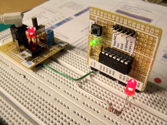
Experimental Setup:
Connect the output of potentiometer (POT2) to AN0 (pin 7). GP5 (pin 2) will serve as TX pin for Software UART so connect it to input Tx of TTL to RS232 Level Shifter circuit. Also connect Rx (2) and Gnd (5) of a RS232 port to the board. This is similar to what we did in Experiment No. 2.
Software:
/*
PIC12F683 Experiment Board
Experimen No. 3 : Read analog voltage from AN0 and diplay
on Hyperterminal window on PC using Software UART.
Date: 06/25/2010
*/
char Message1[] = "Digital Value= ";
unsigned int adc_value, backup=0 ;
char *temp = "0000", error;
int i;
void main() {
CMCON0 = 7;
TRISIO = 11; // GPIO 0, 1, 3 Inputs; Rest are O/Ps
ANSEL = 0x01;
GPIO = 0;
// Define GPIO.3 as UART Rx, and 5 as Tx
error = Soft_UART_Init(&GPIO,3, 5, 9600, 0 );
Delay_ms(100);
do {
adc_value = ADC_Read(0);
if(adc_value != backup) {
if (adc_value/1000)
temp[0] = adc_value/1000 + 48;
else
temp[0] = '0';
temp[1] = (adc_value/100)%10 + 48;
temp[2] = (adc_value/10)%10 + 48;
temp[3] = adc_value%10 + 48;
for (i=0; i<= 13; i++) {
Soft_UART_Write(Message1[i]);
Delay_ms(50);
}
for (i=0; i<= 3; i++) {
Soft_UART_Write(temp[i]);
Delay_ms(50);
}
Soft_UART_Write(10); // Line Feed
Soft_UART_Write(13); // Carriage Return
backup = adc_value;
}
delay_ms(100);
} while(1);
}
Output:
The digital value of input analog voltage will be displayed on hyperterminal window. The digital value will have range from 0-1023 (10-bit ADC).


2 comments:
That's so cool indeed. Amazing creation! I wanna make one for my own too.
discounted digital board
Hi Raj,
Thank you very much for sharing your ideas. I am a newbie to programming and successfully using it on 16F684 ; could you tell me how to modify your code to display analog voltage from one more channel, that is 2 analog voltages simultaneously.
Thanks in advance.
Sam.
Post a Comment